
Archimate with EA Tool
- Anand Nerurkar
- Aug 15, 2023
- 3 min read

Updated: Sep 21, 2023
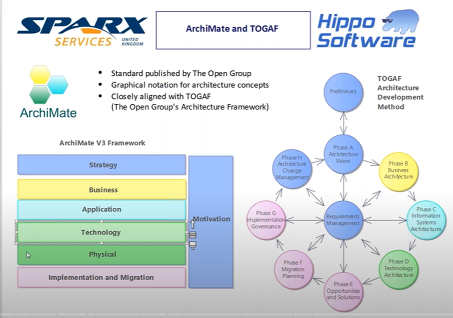
ArchiMate® is a graphical language and open standard used to describe Enterprise Architectures, developed and maintained by The Open Group®. It can be used to create a wide range of viewpoints, each relevant to different project and business stakeholders.
These support the activities of business architects, data architects, solution architects, infrastructure architects and enterprise architects.
ArchiMate is used to describe the architecture of organizations - specifically their business processes, organizational structures, information flows, IT systems and technical infrastructure.
Used to document Enterprise Architecture and understand complex dependency exist between people, process, products, application, data , hardware and software.
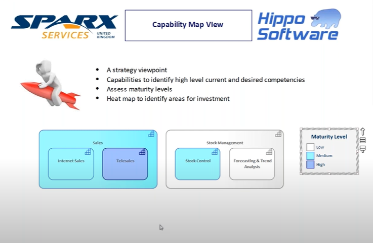
For example : For Strategic planning, we can use Archimate to develop capability map and develop motivational module for project justification.
EA 15 support Archimate 3.1 as below


Business Layer – allow to model organization structure, business process, function, services, products that we offer to our client/partner.
Application Layer – allow to document application landscape and understand interfaces , dependency between application component.
Technology Layer- allow us to catalogue infrastructure for required hardware, software, network and communication.
Strategy layer allow to map capabilities, resources and document course of action resulting from strategic planning.
Motivation layer allow to develop motivation module by documenting stakeholders, business drivers ,goals and justify the project initiative.
It support TOGAF Standard


Active Structure Element are those element that are capable of performing behaviour on passive structure.
For ex:
Active Structure Element for Business layer represent business actor, role who can perform behaviour
Active Structure Element for Application layer represent application component who can perform behaviour
Active Structure Element for Technology layer represent technology node -that represent infrastructure-hardware,software,nw,communication who can perform behaviour
Behaviour represent nature of behaviour being performed.
For business, it may be business function,business services,
For Application, it may be application function,application services
For Technology , it may be technology function,services
Passive structure where behaviour act upon data element.
For business- business object
For application – data object
For technology- artefacts-represent physical storage

In above diagram,
Flower seller is sent to Sell Flowers and update stock level.
Since flower seller ->sell flower->stock level,We can have derived relationship
So we can say Flower seller can update stock level.
Structural element represented by rectangle , behaviour element represented by rounded rectangle.
Please refer below EA repository

Business Layer
Click on new diagram- it support all layer that we discussed

Right click on business action as below

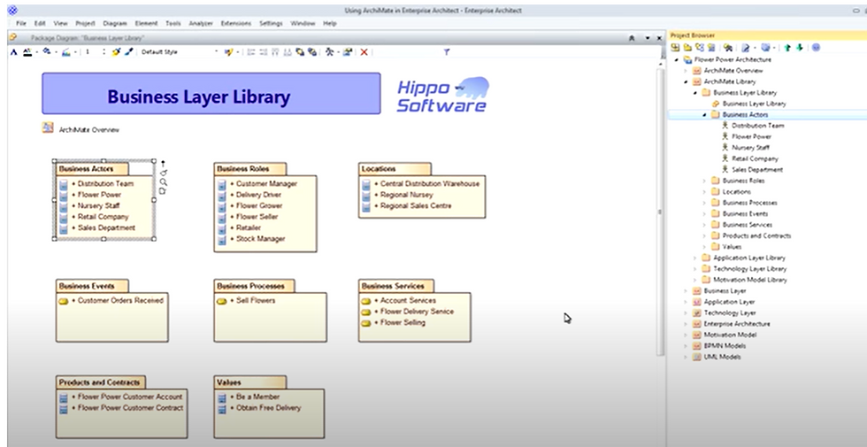
We can use project browser to create various viewpoints
Organization Viewpoint
--show organization strcutor,actor, their role and location as below

We can use EA matrices like actor-role mapping to create profile and to cross reference module element. If it exist, everything is correct. If missing, then we need to place those missing part. click on open matrix profile -actor to role

In above case ,we created profile to show business actor -to -role as per diagram.This should get opened when we cross reference it. If it is missing , then we need to create it and link it.

In above diagram, we make use of tracibility to find out tracibility on the right side panel.
we can also use relation ship matrix for the above by clicking on matrix as below


drag business layer on it ,set it as source


similarly drag business layer on target,set it as target and type as business role, link as assignment
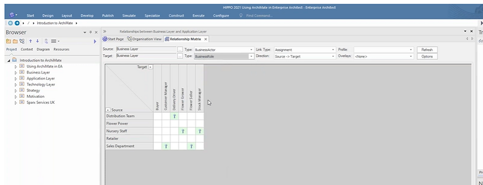
we can see abobe relationship matrix where actor-role mapping is created as per requirement.
We can also see missing element in this by going to options->


we can highlight source and target which does not have any relationship as above option.

Blue and pink color indicate something is missing information from model.
For ex: Retailer is sent to Buyer business role is missing, so we can select that ontersection,create new relationship there

save this as matrix profile


In above diagram, Flower seller within sales department is a carrier to external partner -retailer thorugh business process Sell Flowers which is divided into 3 different subprocess.
1st process Record order is triggered when business event like customer order recived. This subprocess is then linked to bpmn module for the record order process.
Right click on it -link it to bpms module for each of the subprocess, will take you to that process.

Select composite structure diagram-

Select bpmn module -record order


Click on record order-will open bpmn module

Product viewpoint
==
Allow to package up set of services into product for which we have supporting contract and start analyzing value that product offer to customer.

In above diagram, product- flower power customer account allows memer to receive discount and obtain free delivery. This is value( Be A Member) offererd to our customer -retailer
Application Layer
==
Application cooperation viewpoint
==
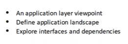
Allow us to understand software applications, interfaces and dependency on other system as below.

Above diagram represent component from UML which we can link it with uml for details as below

Once linked, then clik on that , will take you to class diagram for that compoenent.


Technology Layer
==
Infrastructure Viewpoint
==
Describe hardware,software and communication channel

Strategy Viewpoint
==

we can sue diagram legend to color code

Motivation Viewpoint
==
develop motivational module like stakeholder identification,business driver,goals that we need to achieve , that will justify our project initiative.

we can color code on project justification so that diagram look as per colot code


Comments